HEIGHT MEASUREMENT OF THE
INCOMPLETE FILLINGS AND THE CRATER
DEPTH ALONG THE WELD
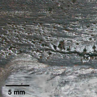
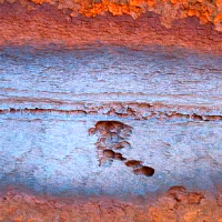
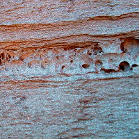
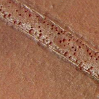
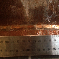
Corrosion layers - corrosion failure in form of a separate layer
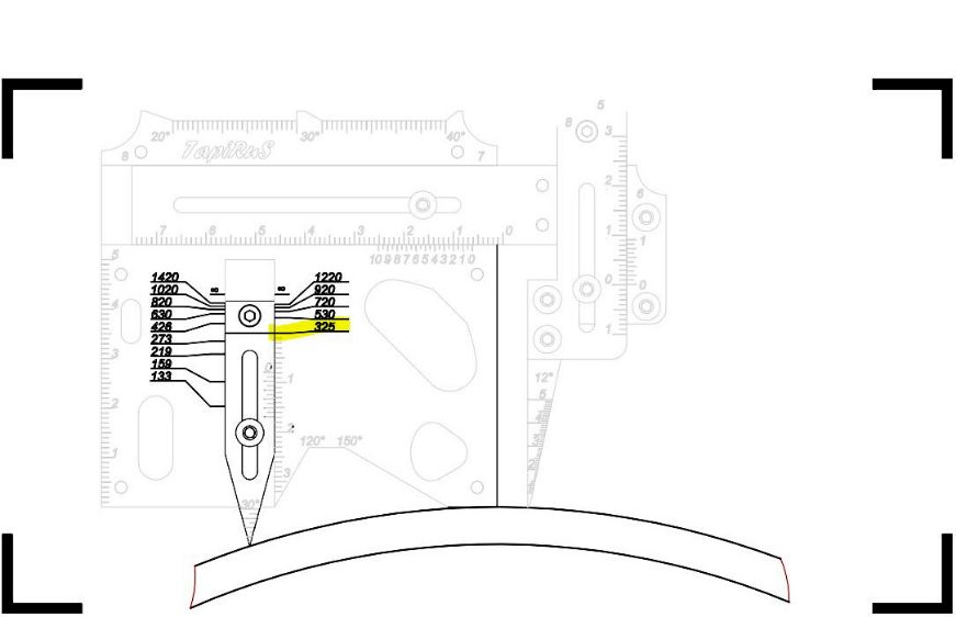
˟ на рисунке риска упора 2 совмещена с диаметром 325 мм
positioning the welding gauge
- Set the welding gauge at the zero position
- Pull the fillet arm 2 out of the main gauge plate 1, matching the mark with a value corresponding to the diameter of the pipe being monitored
- Fix and lock the stop position by tightening the fillet arm rivet 6.
- Position the welding gauge on the test object.
- After rearranging the pivots in the groove located on the right side of the welding gauge, adjust them until they come into contact with the inspected object.
- Lock the pivots in this position as shown by the illustration
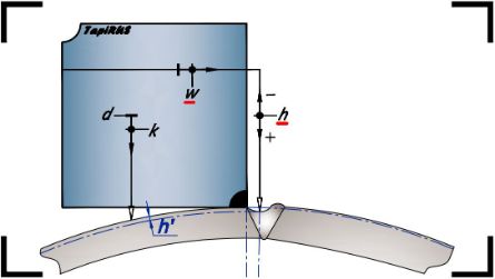
˟ the parameter measured during the monitoring
process is highlighted in red
measurement taking
- Adjust the linear member 3 so that the taper gauge 5 is above the point of measurement (at the point of greatest concavity).
- Lower the top High-Lo arm 4 so that the taper gauge 5 makes contact with the surface of the test object at the point of measurement.
- Take the value of the parameter w from the horizontal scale W, and subsequently the readings of the parameter h – from the vertical scale H.
- To determine the desired parameter h' illustrated use a calculator